
August 2024
Several members have expressed concern that we have not published anything about the Adventure 40 since April.
But this is a case where no news is not bad news, it’s simply no news.
While it’s true that, for a variety of reasons, all outside Maxime’s control, not a lot has happened over the summer, he is still diligently working to secure a builder, has an interested prospect, and is hoping to have good news in September.
Thanks for the update/non-update! I saw you on Morgans Cloud in Mahone Bay today pointing much higher than us on my Beneteau 343. Kayak strapped to the side and dinghy/motor on davits, furling main sail stuck again, and motor sailing- we are a far cry from so much of the wonderful content you write about. That said, we are having such a great week exploring the south shore of Nova Scotia. I can’t wait for more Adventure 40 news.
Hi Mathieu,
Ah, ha! You’re the boat that just beat us to the mooring at Squid Island. I guess we can forgive a member. Glad you are enjoying the province.
Thanks for update. Will be cool to secure a builder.
One quick question I couldn’t find in the A40 documentation, is the steering area below deck isolated from the rest of the boat in case of shaft damage, etc? Watertight bulkhead or similar to stop or reduce flooding?
Hi Kevin,
Yes, and no. I don’t think there will be a watertight bulkhead, although that could change in the final engineering, however the rudder shaft tube top, and top bearing, will be well above the waterline so no seal or gaiter to leak. In fact even if the rudder dropped out of the boat, no water would get in.
On a general bases, water tight bulkheads are something that sounds good, but they tend to impose a big space hit and reduce the designers flexibility in laying things out. The other problem is making them truly watertight. More here: https://www.morganscloud.com/2013/08/19/risk-management-and-watertight-bulkheads/
Thanks John, that detail is very good. I think a better question from me would be what is the approach to rudder safety in case of impact, etc. Most if not all production boats I have seen recently leave the stern open and vulnerable. Given the A40 philosophy it would be good to know the approach like you mention above and wrote about the keel. Another differentiator vs other boats available on the market. A40 keeps checking these types of things off the list.
Hi Kevin,
Yes, good point that we need to think about what happens if the rudder takes a really bad hit. This is way past my engineering pay grade but perhaps we could engineer the rudder shaft tube and supports to be strong enough that the shaft would tend to fail before the tube failed. This is hard to do on most boats, but it might be easier on the A40 because the tube extends far higher than on most boats with a wheel, making the geometry better. Then if the rudder were badly damaged perhaps it could be set up so that it could be dropped out of the boat by the crew and then they could carry on using a galerider to steer. This technique of steering with no rudder has been verified in testing: https://bermudarace.com/emergency-steering-drogue-new-approach/
The possible problem is that Eric Klem tells me that actually designing a weak link that will break when you want it too, and not when you don’t, is tricky.
Anyway, it’s an issue we need to think about.
Maxime: any thoughts?
Hi Kevin and John,
yes, our core idea regarding rudder-damage safety is to have the bearings, the structure that holds them and the upper part of the rudder shaft strongly built. Then, some 50 centimeters below the hull and lower bearing, decrease shaft diameter: strong enough to sustain the possible hydrodynamic loads, but not enough for shock loads that may endanger the upper structure. That way the damage happens low enough to not trigger further damage to the hull, propeller etc. (I think we already discussed this somewhere?)
While mechanical fuses certainly are very difficult to engineer in general, this case is easier.
In addition, there may be the usual metal-free sacrificial section at the very bottom, but I admit that orcas now make me doubt the relevance of a too-easily lost section… Any thoughts welcome!
Regarding watertight bulkheads: so far there is one in the design, well in front of the rudder tube. But as John points out, it comes with a drawback: in our case, if it were not for it, we could have a super large and practical locker for the dinghy etc., in a space that now the bulkhead cuts in two. Assuming things don’t come up very differently in the re-design, we may get the best of both worlds by having the watertight bulkhead travel as a “Z” accross the boat (I mean: at a different location on each side).
Also, given the above, the desirability of this watertight bulkhead may ensue from the risk of damage to the transom, at least as much as from the rudder-related issues.
Hi Maxime,
Thanks for the fill and clarification on that.
By the way, I’m still hoping we can end up with a metals free rudder, or at least a composite shaft, to avoid the problems of water getting into the rudder. I do understand that this might not be practical, and might cause issues for the fuse, but I’m still keen on it as a goal.
Thanks John and Maxime,
It’s great to hear/read the details about the boat. These articles and comments have really built my excitement about the boat as it starts to differentiate from current production boats and pedigree used boats (HR, etc.). The more I learn the details the more the boat checks off the boxes.
Hi Maxime,
A step in the shaft would surely create a stress concentration that can be controlled and is reasonable to manufacture (assuming SS rudder post). One of my first tasks as a newly trained engineer was to design a vane shaft subject to fatigue that needed 2 steps in it and it was an eye opening experience for me as I struggled with making a geometry that wouldn’t fail, it must have taken 100 FEA runs to get it right. Now that I have the experience I do it a lot quicker but still try to avoid steps whenever possible (the machinery I do has a lot of shafts but does not use shafts as fuses).
This got me thinking on what the failure mode is assuming the shaft is weaker than the bearing supports. I assume most failure will be due to the rudder hitting something at speed. If a ductile, solid shaft is used, it will yield but not fully fail and likely leave the rudder jammed against the hull. At best this might leave the rudder stuck in a single position which likely would require pushing it out to allow an emergency steering system to be able to keep the boat straight. At worst, it may punch a hole in the hull and be jammed in the bearings so it can’t be removed easily. On the other hand, if a less ductile material with a larger diameter and thin walls is used, this is more likely to fail catastrophically and separate. This shaft will be more sensitive to damage such as small amounts of corrosion or a careless yard worker nicking it with a tool which makes me not really like this option. And all of this assumes a very hard hit. In a less hard hit, it is possible that the ductile shaft will still be usable but slightly bent and a shaft that fully fails won’t be usable as the rudder won’t be there (for the non-engineers, we try to design things to stay below yield but once they exceed it, the ductile example will absorb a lot more energy before full failure and the question here is what happens past the yield point for structures that may yield at the same time). I guess this is why it is tempting to try to fuse in the blade below the rudder stock and not in the rudder stock itself as you are more likely to end up with something that might give you some steering and is unlikely to prevent an emergency steering arrangement from working although I know of several exceptions to this. My guess is that it is not common to run non-linear plasticity analysis on rudders and even if it was, many of the components don’t have predictable enough properties to make it meaningful so the post-failure condition might not be well known.
I am curious if there is a better way to think about this.
Eric
Hi all,
John: same as you! I don’t have a practical and economic solution so far for all-composite, but have not given up hope!
Kevin: thank you, and glad to hear!!
Eric: many thanks for the input!
Oh yes the stress concentration pattern must be difficult to understand if the step is brutal? Assuming a stainless steel turned stock, I was thinking of a gentle conic short section (with an angle at maybe 20° to the vertical) between the “strong” and “weak” part of the shaft, so that prediction of the moment that triggers yield can almost be done by hand, limiting the subsequent work on computer. Any feedback and input welcome!
Also, we already have a FEA office committed to doing the non-linear analysis of the keel under shock ( https://www.ec2-modelisation.fr/ ), and can ask them of this other mission once the whole discussion with the stock supplier is done.
Hi again,
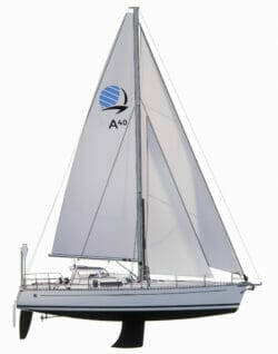
…and I should have started with the beginning: first of all, we give the rudder a slightly lower aspect ratio than often seen – less depth and more fore-and-aft length, as represented at the top of the article. Sure it is a bit less desirable for hydrodynamics, but reduces the efforts and enables a wider shaft. (also, let’s not forget that the vertical distance between the underwater appendages and the sails is the root of all evil!)
Any thoughts welcome!
Interesting discussion. Last month I sailed from Fiji to NZ on a 36foot yacht with a transom hung rudder. The speed and handlof this boat is superb. Nearly 50 year old NZ designed and built. 200 mile a day capable yacht. When she was younger raced Auckland to Suva (1150nautical miles)in 6.5 days. Nothing wrong with the performance of a transom hung rudder!
Simple to maintain and repair. Hooked up to a below decks autopilot in a very simple elegant way Possible to remove easily in or out of the water without digging a hole or using a travel lift. Gets rid of a hole in the boat that can potentially sink you.
Cheap to build and lends itself to full composite construction. Timber rudder stock, gudgeons and pintels made in bronze all original. Boat has circumnavigated shorthanded via the Horn. Simple, strong cheap and tough. Worth some serious thought.
Hi Peter,
Yes, there’s a lot to like about transom hung rudders, but after considering one seriously the French team have decided that’s not the best option for the A40. More here: https://www.morganscloud.com/2022/03/11/adventure-40-rudder-and-steering-gear/
Hi Maxime,
Yes, 20° is a common taper half angle on shafts and is probably a good starting point. If you draw the constant stress lines in cross-section, you find that the lines don’t like to follow any steeper of an angle and you just get a big stiff spot that doesn’t do much for you. Of course, one of the main reasons for steps in shafts is to provide a shoulder for things like bearings so an awful lot of steps are a full 90° and a real pain to design. I assume you can do a fillet style stress relief with a good radius and this should be fine, I would definitely try to avoid any undercut ones which will be points for corrosion.
As you say, it should be possible to look at the elastic region by hand calc or very simple FEA and get the design close. Personally, I would be nervous to include a fuse without then doing the non-linear analysis to understand the true failure mode in the plastic region. I have heard multiple accounts of people being unable to control boats where either the rudder shaft bent and jammed or the breakaway lower section only partially broke away and the steering force from this was greater than any counter force that could be applied including emergency rudders. I don’t know how common these issues are but my general feeling is that we shouldn’t try to put a failure somewhere without knowing the consequences. Keeping the water out has to be more important than steering but steering including emergency steering has to still be one of the most important things.
Good luck.
Eric
Hi Eric,
thank you for the comment and for the confirmation on the 20° angle, much appreciated!!
And I’m in agreement on the rest.
To the others, a clarification: we speak of fuse here, but it is sized as “normal” on other boats (there’s an ISO standard on this). It is a fuse only in comparison to the unusually beefier construction of the upper rudder and of the bearings.